Tools
-
-
Phillips Screwdriver
-
Flathead Screwdriver
- Wire Cutter / Crimper
-
Dremel / Angle Grinder (depends on light choice)
-
Silicone (not include with kit)
- Switch, Fuse, Relay (not include with kit)
- See wiring section to determine if this is needed.
-
Preparation Notes
-
-
Lay out your kit components, arranging them according to their respective sides. Components specific for the passenger (right) side are marked with a red dot.
-
Insert nuts into each of the 14 designated locations:
-
-
2 nuts are located on the back of block E.
-
The remaining nuts locations are found on the back plates.
-
To ensure a snug fit for the nut into its location, twist a screw into the nut, then leverage the nut into its spot. Then remove the screw.
-
-
-
Initial Setup
-
-
Remove the front grill carefully to avoid bending or damaging the plastic tabs near the bottom corners.
-
Detach the headlight cages by removing the four retaining screws.
-
Disconnect the wiring, being mindful of old, brittle plastic plugs.
-
Remove the headlights from their mounts at the light connection points:
-
-
Be cautious not to break the white mounts attached to the cage as they are essential for the frame kit to work.
- To detach the attachment point caps at the light, place a screw driver under the white tabs on the backside. Gently twist while applying pressure to the top of the adjuster head. As a section detaches, then repeat for the the remaining sections.
-
-
-
Take off the plastic caps from the adjustment heads. These are not needed in the new kit.
-
Identify the three mounting points for the new assembly:
-
-
#1: A single mount on one side.
-
#2 and #3: Positioned on the opposite side, with #2 directly across from #1 and #3 adjacent to #2.
-
-
- Now is a great time to to inspect your adjusters. Do you need any new ones? So they all move freely? You may want to add some WD40 or similar to those adjusters. Carefully!! get them moving.
- Adjust each of the adjustment screws to match the height of the adjustment screw that is stationary within the set.
-
Cage Modification
-
-
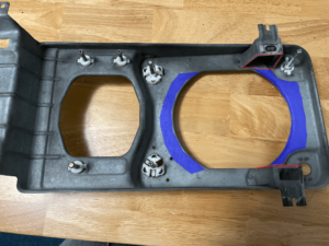
Widening the Grill Attachment Points
-
-
See (red) in image below or the video for visual on the points to remove metal from.
-
Remove approximately 1/16″ from each side, or about half the distance from the edge to the cut-out.
-
Take your time and keep checking the fit as you make additional adjustments. Do not cut through
-
-
-
Adjusting for Depth or Unique Shapes
-
- Remove the entire lip of the circle or more to create enough space for the headlight to fit. An angle grinder or cutoff wheel works great.
- See (blue) in image below.
-
-
Fog Lights Assembly
-
- Install the nuts on the backside.
-
Place the backplate into the cage, ensuring the “Up” marking is visible. Attach the two hooks to the upper mount points (#2 and #3).
-
Attach a block C to the #1 adjustment mount, then press into place on the backplate where indicated with a C. It may not hold very well. This is ok.
-
Insert the fog light into the front frame from the rear, ensuring the light handle faces the center of the van. **Do not install the brackets that come with the lights.
-
- The backplate will compress around the handle. Some flexing of the backplate may occur as it compresses.
- **Fog #13 does require the mounting bracket to be installed and shifted forward on the handle.
-
-
Connect the one A and two B blocks to the back of the front frame. Align the blocks with their respective A or B markings, ensuring the letter is facing the the direction of the light.
-
Position the front frame on to the adjustment screws and backplate. Position loose tabs roughly into their locations. Insert a 1.5″ stainless steel machine screw into each of the three holes.
-
-
Slowly tighten the screws while ensuring the adjustment point locks engage snugly around the adjustment mount head.
-
Avoid overtightening. At no point should there be need for more than finger strength tightening. Use your pinky beneath each screw to help maintain alignment as you tighten.
- There should be no gaps around the pieces and the adjusters. If there is, loosen it up and determine where the snag is. Sometimes it just needs and adjustment, then retighten.
-
-
- Adjust the light even in the housing. Some lights have a sloped trim, so focus on getting the face of the light flush.
- Apply a bead of silicone to the backside where the light meets the housing. This will prevent the light from shifting.
Headlight Assembly
-
-
Attach a block E to the #3 adjustment mount, and set at about a 45 degree angle. Be sure to have the nut installed.
-
Place the backplate into the cage, securing it to the #1 and #2 adjusters.
-
Press the #3 block E into the backplate, ensuring it is flush and not crooked.
- Position the light on the frame.
-
Secure the front frame onto the backplate.
- If the light seems loose within the frame after tightening, some foam tape and be used to take up space. Place in the corners. Most lights do not require this.
-
Insert machine screws through the four corners of the frame:
-
-
Use 1.25″ screws for #1 and its adjacent location.
-
Slowly tighten the screws round robin, ensuring the adjustment point locks engage snugly around the adjustment mount head.
-
Avoid overtightening. Finger strength only. Use your pinky beneath each screw to help maintain alignment.
-
-
- The kit should go together with no gaps in the corners. If one side is not going even, loose everything, ensure things look goo and try again.
- Once all tightened up, Adjust #1 & #3 adjusters down to be about 1/2 from the cage. This is a good starting point. The edge of the #3 frame should be about 1/8 – 1/4 inch away from the fog light frame.
-
Install Headlights
-
- Connect the headlight and fog light wiring
-
Reinstall the headlight bucket, ensuring it is securely fitted.
-
Attach the grill, ensuring a even fit over the new light frame. Due to van aging and weather exposure, some grills may have changed shape. You should expect a snug fit. Shift and wiggle, shift and wiggle.
-
-
If necessary, gently shift the grill in all directions to ensure proper alignment.
- If necessary, move headlight cage a small bit in its location, then try the grill on.
-
-
Vanagon stock headlight wiring uses the 9007/9004 standard, with three wires:
-
- Brown: Ground
- White: High Beam
- Yellow: Low Beam
7×5 LED headlights follow the 9003/H4 standard. When looking at the back of the plug (flat side down):
-
- Left: Ground
- Middle: Low Beam
- Right: High Beam
Wagenvolx offers pre-made 9007 to H4 wiring adapters for sale.

Creating a Wiring Adapter
Wagenvolx offers pre-made 9007 to H4 wiring adapters for sale.
Depending on your level of electrical expertise, you can choose to create your own wiring adapter. Options include:
-
- Soldering the wires for a permanent connection.
- Using crimped connectors for ease of assembly.
Regardless of the method, make sure to:
-
- Apply dielectric grease to prevent corrosion.
- Use heat shrink tubing to protect connections.
- Avoid leaving any wires exposed.
The stock High Beam plug may no longer be needed, but should remain intact. Do not cut it. – See the Fog light section below for possible use.
Wiring Daytime Running Lights (DRL) and Integrated Blinkers
For LED headlights with DRL and blinker integration, this what I did on my van. You should consult your mechanic for final decisions on your van.
I connected them to the adjacent side marker and blinker wiring to activate the DRL with my parking lights.
-
- Detach the Side Marker Housing:
-
- Unscrew the housing from the van and detach it from the light socket.
- Pull back the rubber grommet around the wiring approximately 6 inches to expose the wires.
-
- Identify the Wires:
-
- Left Side:
- Brown: Ground
- GY/BK: Parking Light
- BK/W: Turn Signal
- Right Side:
- Brown: Ground
- GY/R: Parking Light
- BK/G: Turn Signal
- Left Side:
-
- Prepare New Wires:
-
- Cut wires long enough to run between the side marker and the headlight.
- Poke two small holes in the back of the rubber grommet and feed the new wires through until they match the terminal length.
-
- Merge Wires:
-
- Connect the new wires to the existing wires using splice connectors, soldering, or female spade terminals.
- Pull the rubber grommet back down to protect the connections.
-
- Attach Male Spades:
-
- Securely attach male spades to the new DRL and blinker wires, leaving enough flexibility to adjust if needed.
- Before fully tightening connections, test the wiring to ensure the DRL and blinker function correctly.
-
- Detach the Side Marker Housing:
Fog Light Wiring Instructions
For the fog lights, it is recommended to install a dedicated switch connected to a fuse and relay for proper operation. There is a great write up on how to wire your fog lights on thesamba.com. This article on the Vanagon fuse box is also very helpful.
There is also an alternative way using the stock Vanagon high beam wiring.
New Switch Version
-
- Install a Switch:
-
- Use a dashboard-mounted or other accessible switch to control the fog lights.
-
- Connect the Relay:
-
- Relay (86): Connect to the switch.
- Relay (85): Ground connection.
- Relay (30): Connect to a power source with an appropriate fuse close to the source.
- Relay (87): Connect to the positive terminal of the fog lights.
-
- Ground the Fog Lights:
-
- The negative wire of the fog lights can be grounded to the vehicle’s frame.
- Alternatively, connect the negative wire to the leftover High Beam brown wire socket using a spade terminal.
-
- Use Proper Wire Gauge:
-
- Ensure the wiring is appropriately sized for the current draw to prevent overheating or damage.
-
- Install a Switch:
High Beam Version
The new headlight comes with an integrated high beam, so the old high beam wiring is not needed. Given that the Fog Light are more like a super High Beam, some users of the kit have chosen to wire their fog lights into the left over high beam socket. This way when they turn their high beams, the fog come on also.